Support load calculation per iec 61537 one or more spans iec 61537 7 3i.
Cable tray support span calculation.
Calculate cable tray width calculate cable tray area calculate cable tray length calculate cable tray weight calculate remaining width of cable tray calculate remaining area of cable tray free download.
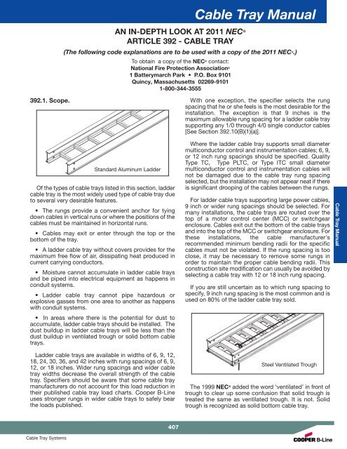
610mm of a splice on straight sections and the span between supports should not exceed the length of tray.
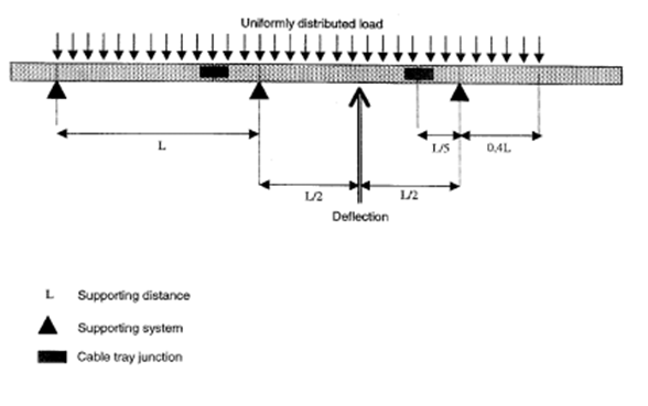
A typical multi span cable ladder or cable tray installation behaves largely as a continuous beam.
Common tools for installation 04 section d 2.
Receiving and unloading 03 section c.
This classification is based on the working load the total weight of the cables and the support span the distance between supports.
On tue dec 2 2014 at 7 52 pm electrical notes articles wrote.
Installation 03 section d 1.
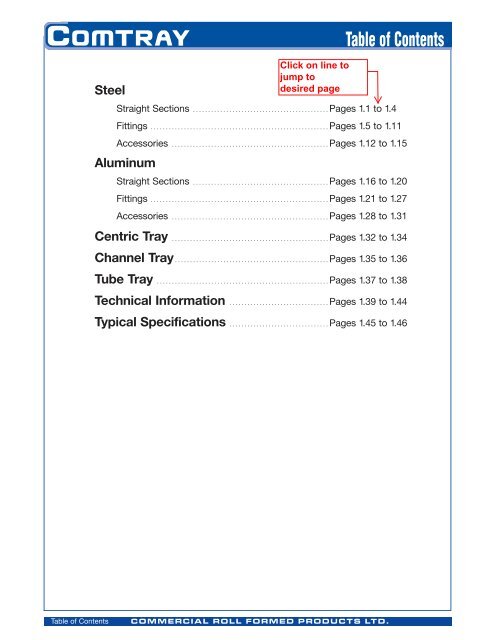
1 table of contents 02 section a.
The nema classes are based on cable loads of 50 75 and 100 per lineal foot.
Installation of support structure 09 section d 3.
Vertical cable tray elbows at the bottom of runs should be supported at the top of the elbow and within 610mm of the joint at the bottom of the elbow.
Cable load working load the cable load or the working load is the total weight of the cables to be placed in the tray.
Straight length installation 16 section d 4.
Quick tray fill and load calculations anchor must be evaluated separately supports should be placed within 24 in 610mm of a splice on straight.
The greater the number of spans the closer the similarity.
Supports should be placed within 24 in.
Cable support systems in the international world iec61537 2004.
Vertical cable tray elbows at the top of runs should be supported at the joint on each end.
6 cable ladder and cable tray systems including channel support systems and other associated supports definitions and abbreviations accessory component used for a supplementary function e g.
Fittings installation 23 section d 5.
For support spans greater than 5 feet 1 5m cable loads must be evaluated to ensure that the span between the supports is suitable for the load the support and anchor must be evaluated separately.
Weight on support weight of span 2 cable tray maximum load in lb ft according to span catalog number 5 ft 6 ft 7 ft 8 ft 9 ft 10 ft.
Intermediate support for upper tray required on piperacks over 6096mm wide.
Field modifications 25 section d 6.
Ancillary products accessories.
Introduction 02 section b.
However in practice a run must contain joints and it can also never be of infinite length so it is important to appreciate how its characteristics vary from span to span and how these.