Cable Gland Installation Procedure
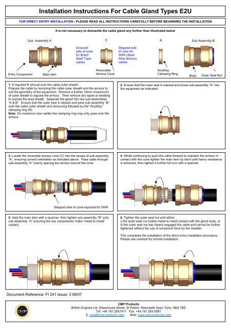
Installation Instructions For Cable Gland Types E2u Cmp Products
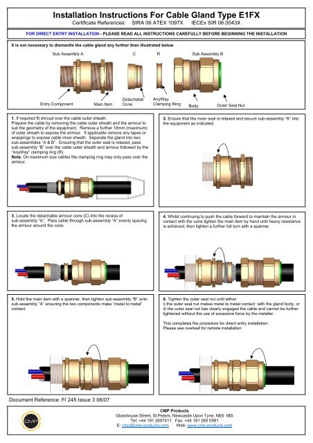
Installation Instructions For Cable Gland Type E1fx Cmp Products

Installation Instructions For Cable Gland Type Cx Cmp Products
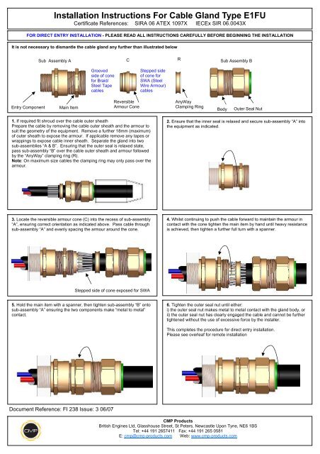
Installation Instructions For Cable Gland Type E1fu Cmp Products
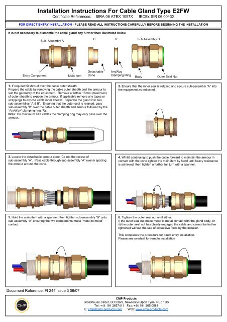
Installation Instructions For Cable Gland Type E2fw Cmp Products
What Is A Cable Gland Instrumentation Tools

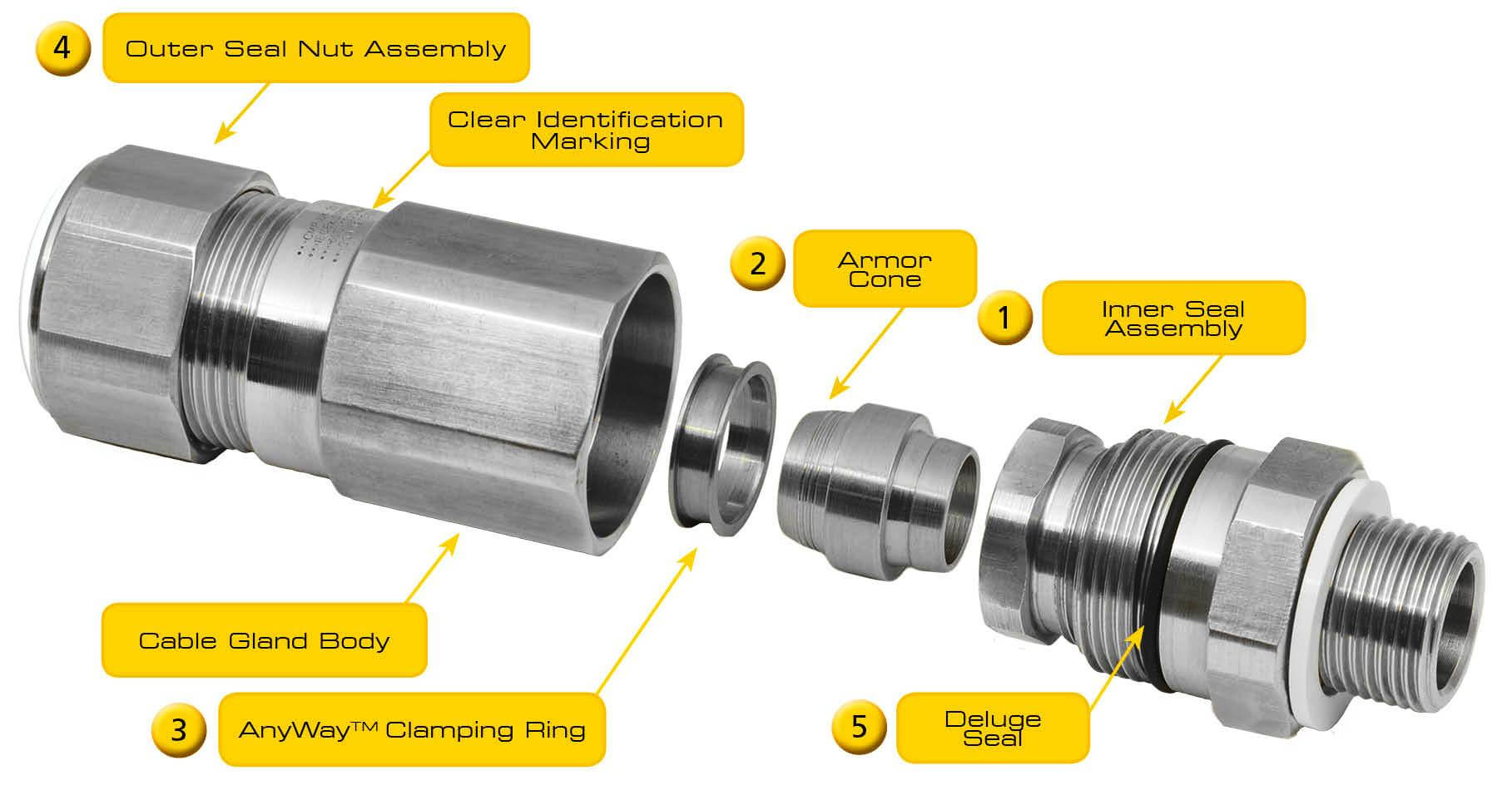
Installation of cable gland type t3cds installation instructions 1 select the correct cable gland size using physical dimensions of the cable cross referenced against the selection table opposite.
Cable gland installation procedure.

Steel Wire Armour Cables Maintaining Earth Continuity
Https Www Nexans Co Nz Eservice Newzealand En Nz Documentdownload 73320 Installation Instructions
Cmp A2f Cable Glands Installation Instruction Manualzz
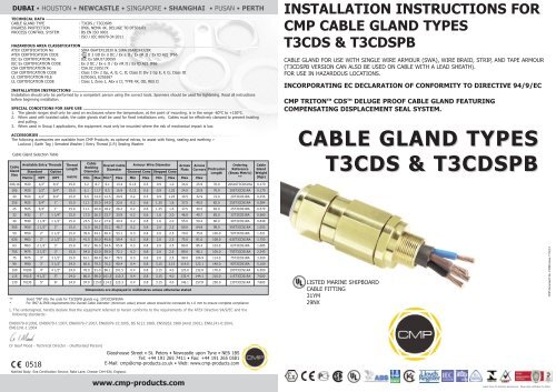
T3cds Installation Instructions Cmp Products
Source : pinterest.com
